001
GENERAL
The access floor system as called for in this specification and
shown on drawings shall be Access Floors International Cementitious filled Steel
panels type ASF/ Hollow Steel panels type ASH series.
The Access Floors International
ASF/ASH access flooring system shall consist of modular panels positioned and
supported at each corner by an understructure of all steel pedestals/and stringers.
Each
pnel shall be easily removable by one person using a lifting device. All panels
shall be interchangeable except where cut for particular floor positions.
The
finished floor height slab to panel surface shall be...... mm and the complete
floor system shall be rigid, free of rattles, sqeaks and rocking panels. The overall
floor shall be level within 1.6mm in 3m.
The grade shall be light/medium/heavy/extra
heavy as per MOB PF2 PS/SPU 1992 and comply with the BCA.
002
THE PANELS
All panels shall be of all steel construction/and filled with
a light weight cementitious material.
Size: 500mm x 500mm/600mm x 600mm/610mm
x 610mm.
TYPE:
MATRIX
ASF800 - Light to medium grade, constructed with a 0.9mm steel bottom pan and
0.8mm top plate.
Concentrated load minimum 3.5kn over 25mm x 25mm.
MATRIX
ASF1000 - Medium to heavy grade, constructed with a 1.0mm steel bottom pan and
0.9mm top plate.
Concentrated load minimum 4.4kn over 25mm x 25mm.
MATRIX
ASF1250 - Heavy grade, constructed with a 1.2mm steel bottom pan and 1.2mm top
plate.
Concentrated load minimum 5.4kn over 25mm x 25mm.
MATRIX ASF1500
- Heavy to extra heavy grade, constructed with a 1.2mm steel bottom pan and 1.4mm
top plate.
Concentrated load minimum 6.7kn over 25mm x 25mm.
THICKNESS (without
covering): All 33mm nominal.
Mass:
MATRIX
ASF800 - Cementitious 12.8kg per panel.
MATRIX ASH1000 - Hollow 7.7kg per panel.
MATRIX
ASF1000 - Cementitious 14.2kg per panel.
MATRIX ASH1250 - Hollow 8.7kg per
panel.
MATRIX ASF1250 - Cementitious 16.0kg per panel.
MATRIX ASH1500 -
Hollow 9.8kg per panel.
MATRIX ASF1500 - Cementitious 19.3kg per panel.
Finish:
Panels
shall be protected against corrosion with an electrostatically applied powder-coat-baked
epoxy paint.
Covering:
The
floor panels shall be finished with High Pressure Laminate/carpet/vinyl tiles/natural
stone/ceramic tiles/marble.
State type, colour, pattern and thickness
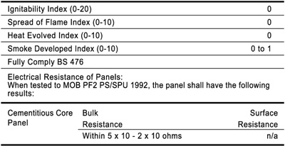
Fire
Performance:
When subjected to "Tests for Early Fire Hazard Properites
of Materials" - AS1530, Part 3 the panels, excluding covering, shall have
the indices no greater than: 
003
UNDERSTRUCTURE
The Pedestal Assembly:
Pedestals shall be
all-steel construction to avoid electrolysis, the head plate accurately die-formed
of 3mm/4mm x 75mm x 75mm steel and shall accept bolt-on stringers or cornerlock
panels.
A 20mm threaded stud with a vibration-proof height adjusting not completing
the pedestal head. The
pedestal head shall be supported within a 25mm diameter round tuble, continuously
fillet-welded to a 100mm x 100mm x 3mm pedestal base.
The pedestal shall be
zinc-plated to provide a corrosion-resistant finish. Overall adjustment shall
be of approximately 75mm.
The Stringer:
The galvanised steel
roll-formed box section shall be supplied in 500mm/600mm/610mm lengths with a
die-punched countersunk hole at either end to receive the screw. The 15mm x 32mm
stringer t be used with all rigid grid applications forming a modular grid pattern
under the edges of all floor panels.
The Fasteners:
A 50mm countersunk-head
screw shall be used for both the rigid grid type installation - where it is used
to secure the stringer, and the cornerlock bare panel-type installation where
it is used to secure the panel to the pedestal head.
Electrical:
The
understructure shall be connected to the building earth by an electrical contractor
to provide electrical continuity throughout the system.
004
ACCESSORIES
Supply......perforated panels with/without shade dampers and
a 25% free flow area/......aluminium grilles......mm x ......mm/
Supply......100mm
diameter round plastic cable outlet grommets.
Supply......suction lifters/......carpeted
panel pin lifters.
Supply......spare panels.
Supply......ramps and......steps
and install all as shown on the drawings.
005
INSTALLATION
Installation shall be as per manufacturer's recommendations
and directed by an experienced supervisor.
The work area is to be clear and
free of other trades, their debris and other materials before access floor installation
is to commence.
Variations will not be permitted without the owner's representative's
instructions in writing.
Cable hole edges shall be properly trimmed with plastic
angle to prevent cable damage.
Pedestals shall be firmly fixed to the slab
with a suitable adhesive. Ths slab shall be vaccum-cleaned and sealed against
dust and moisture intrusion with a suitable sovlant.
Acceptance:
Prior to
leaving the site the installer shall inspect the installation in the company of
the owner's representative and acceptance or otherwise shall be recorded in writing.
006
SUBMITTALS
1 At least 3 other installations of a similar floor type will
be required as examples.
2 Samples of pedestals, stringers and panel will be
submitted.
3 Carpet, vinyl or HPL samples must be supplied for colour/pattern
selection.
4 Proof of all test results must be shown
007
MACHINE INSTALLATION
During the movement of heavy loads over the
Access
Floors International access floor, protection will be supplied by the owner to
protect surface materials.
Cable holes will be cut and trimmed with appropriate
material on site as indicated by the owner's representative. | 
